Central Vacuum Inlet Valve Installation Instructions


Install only on a normal 120V, 60Hz, 7 amp supply protected by a maximum 15 amp over-current protective device. The pin connector on this type of wall valve is intended for use on a normal 120V, 60Hz, 7 amp supply only. It is required to be wired by a qualified electrician and is required to conform to local electrical codes.
WARNING: To reduce risk of fire and electric shock, connect only Allegro Super Deluxe "Direct Connect" electric hose. Do not operate hoses on wet surfaces.
New Construction
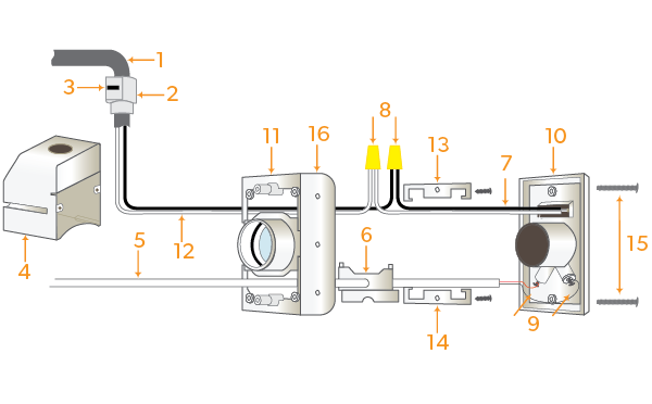
| 1. | Install building wire conductors [1] through the approved type electrical connector [2] (supplied) until they produce approximately six (6) inches from connector. Seat connector firmly into the opening. a top the wiring compartment [4]. Insert and secure locking tab [3]. |
| 2. | Splice wires [7] from inlet valve receptacle to the protruding building wire conductors with #31 twist on wire connectors [8] (not supplied.) |
| NOTE: White wire to White wire & Black wire to Black wire. | |
| 3. | Feed low voltage wires [5] through opening in the LVT cover plate [6] and connect to the two contact screws of the inlet valve face plate [9]. |
| 4. | Push inlet valve face plate [10] into mounting plate [11]. At the same time, push electrical conductors [12] and connectors [8] into wiring compartment [4]. Back out the two (2) screws that hold the wiring compartment in place. Slip upper finished wall clip [13] with mounting screws (supplied). |
| 5. | Install the lower finished wall clip [14] with screws (supplied). |
| 6. | Secure inlet valve face plate [10] to mounting plate [11] using the two supplied colour matched screws [15]. |
Existing Construction
After pipe, low voltage relay control wire, electrical building wires and opening in wall has be cut:
| 1. | Remove mounting plate nailing flange [16]. Use a hack saw or score with razor knife along dotted line and snap off. |
| 2. | Repeat Step #1 (from New Construction) |
| 3. | Install modified mounting plate with short 90° elbow glued in position into wall opening. |
| 4. | Repeat Steps #2-6 (from New Construction) |


