Central Vacuum Standard Inlet Valve / Installation Instructions
|
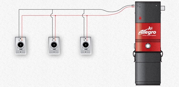
How to Install Central Vacuum Wall Inlet Valves ln order to operate the central vacuum power unit remotely from inside your home you would need to complete the low-voltage 24v dc wiring. The Wall lnlet Valves (Faceplates) ZIC010 are connected together in parallel so each Wall lnlet Valve (Faceplate) could operate the system independenily. The low-voltage wiring is terminated at the 24 v dc Power Unit low-voltage connections. |
|
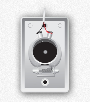
For the low voltage connections please follow the diagram below:
|
|
IMPORTANT:1) Do not completely remove low-voltage connection screws to avoid losing the internal spring and the contact mechanism. 2) Turn the low-voltage wire around connection screws in clockwise direction. 3) Make sure that there are no exposed copper to touch each other and make connection per Fig.1. This will keep the Power Unit running constantly. 4) If you home is roughed in for central vacuum piping and the low-voltage wire is four conductor instead of two. You can pair any two together as long as you stay with the same colors throughout the house. Or just use any same two colors throughout. Central Vacuum Low-Voltage Wire Specifications:22 gauge Two Conductor
|


